Machine Language
Written politely 2021-09-12.
Overview
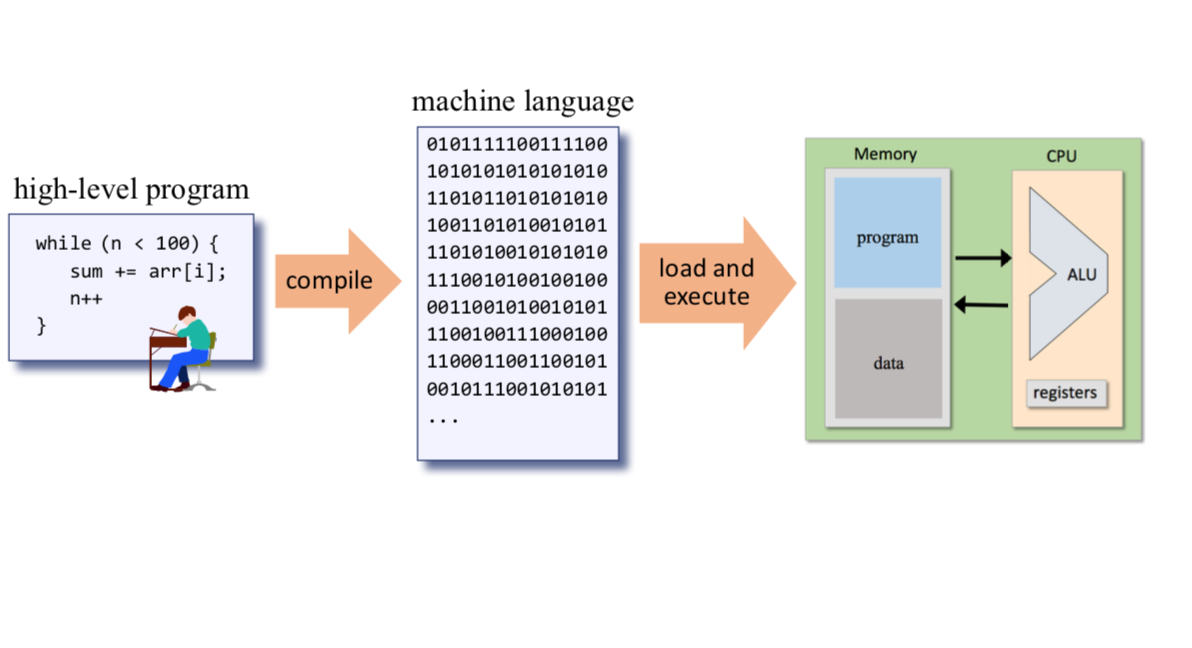
A set of instructions in a program tells a computer what to do, in what order to do things, and where any data should be put into storage for later reference. The software needs to be able to control the hardware. In order to do that, an assembler compiles higher-order software programming languages into machine language basically like this.
Continuing from the previous post about creating memory, if this is your first time reading a post in this series on Building a Modern Computer, I would suggest to begin starting at the beginning.
Elements
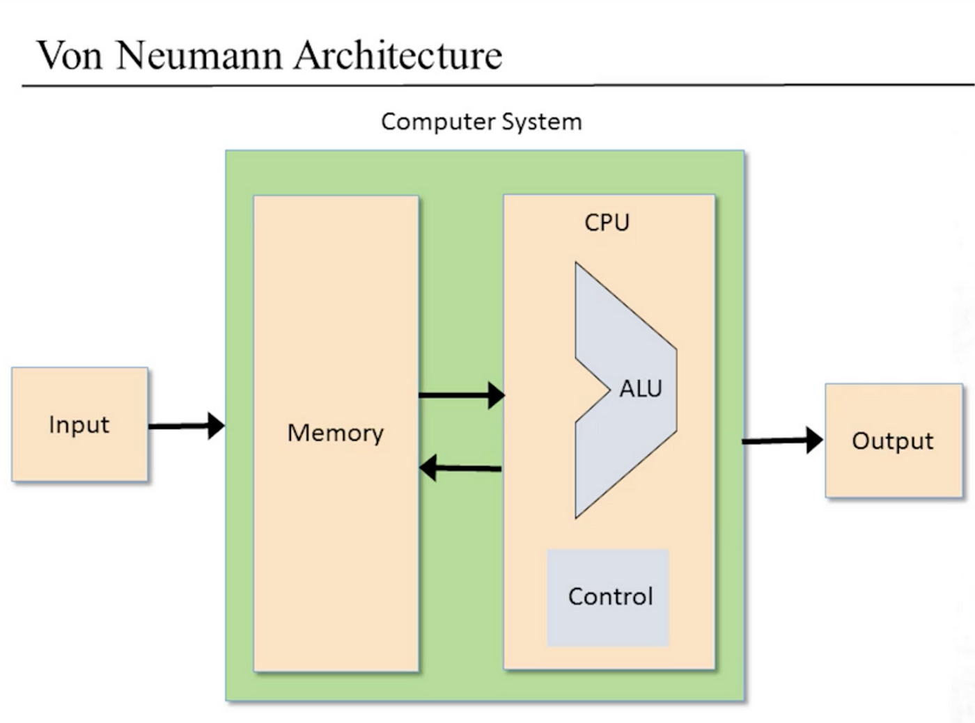
There are several elements to machine language operations. Machine operations, such as mathematical and logical operations, and flow control. A memory hierarchy, from registers, to cache, main memory and hard disk exist assist in data recall and recording. Input and output devices, such as a keyboard, mouse, monitor, and anything you attach to your computer can be accessed with machine language.
Project Outlook
Chapter 4 and the accompanying videos on Coursera set up the user with the foundation on how to complete the projects without going into the finer details on how to fully finish them. The instructors suggest to first put into pseudo-code the steps needed to finish the task before writing them in machine language. The machine language is used to control various hardware in the computer, such as memory units (RAM and ROM), the Central Processing Unit (CPU), the program counter (PC), registers (such as those constructed in the previous chapter), and any input/output devices (such as a display and a keyboard).
In order to control the various parts of a computer, assembly language is compiled into binary code inside the computer. Develoeprs have a choice of two ways to display and interact with machine language. One way is with 16-bit binary code (16-bit because in this case because of the HACK computer used in the program), like this 16-bit binary number 101011000100001, and the other is with a more readable syntax called assembly language. Rarely do developers actual write much code in binary, but understanding how it works is fundamental to understanding how computers function. Developers use assembly languages that allow humans to more easily see, understand, and manipulate machine language. Computers are built to use binary code, but actually using binary code to write machine language would be very slow and (probably) error prone for a developer, even after gaining lots of experience writing and manipulating binary code.
Assembly Code for the Hack Computer
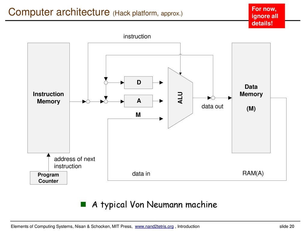
There are three sets of registers to read/write from in the hack computer. A, or the numeric value of the selected RAM/ROM memory register. M for the value stored in the currently selected memory register. And D, for a data register that stores one value at a time and can be used to manipulate the values before taking action on them. Here is a great diagram to show this relationship between the different registers.
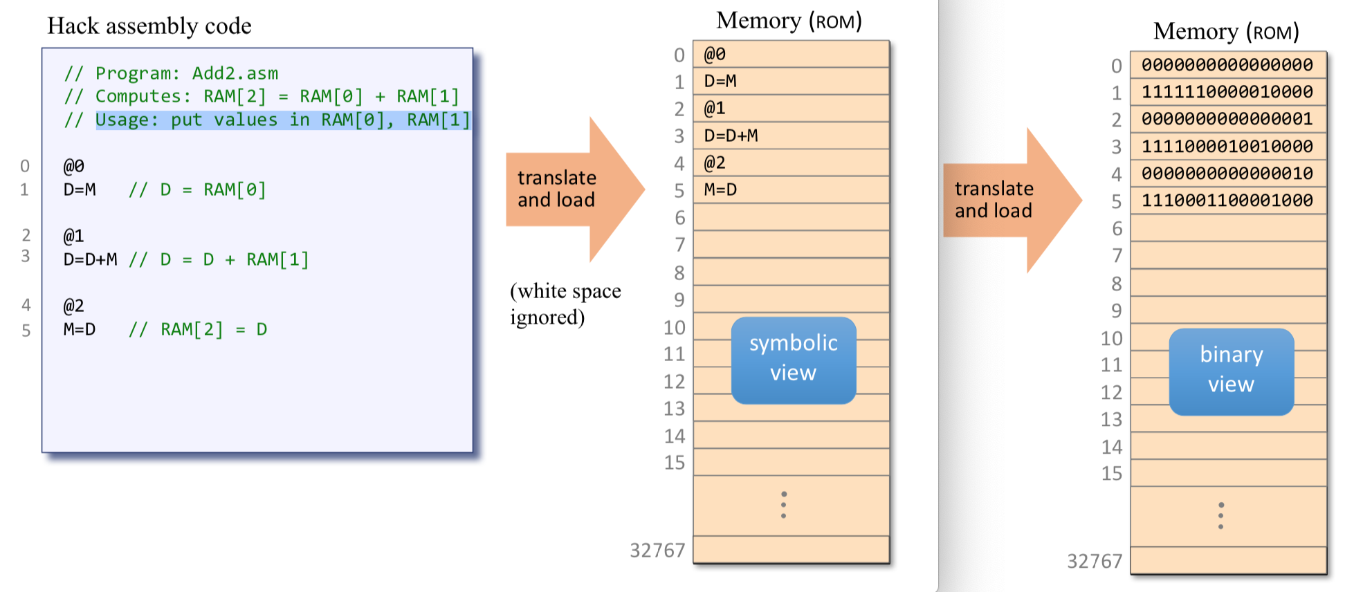
There is a set of registers that act as the RAM for this project. To access each RAM slot in machine language, first access the register number which is represented by the @ symbol. For example, to access the register at register number 4, the code looks like this @4. That will set the A register equal to 4 and M will represent the value stored in register 4. The D register can only hold a single value at a time and is used for short-term storage of a value for use in the other registers. For instance, to set the D value to the value in register 4, it is simply @4 and then the next line would be D=M or the D register is equal to the value in the register 4 memory. Then, to alter that value just add to it, like this, D=D+M.
In addition to setting and updating values, there are pointers and loops in our assembly language that we can use to accomplish the project tasks.
Pointers can be set with the @xxx with xxx being whatever variable is selected. For instance, @var would select the register for that pointer. The data for that pointer can still be manipulated by doing D=M to set the D register value to the value stored in the @var register, and M=D to set the @var register value to the value stored in the D register.
Loops are referenced similar to Pointers but using all Capital letters for the variable name. To define a loop, it would be (LOOP) with the body of the loop indented in one tab stop from the characters of (LOOP). To repeat a loop, put 0:JMP at the end of the loop, because the JMP indicates to always jump. The 0:JMP part tells the instruction memory to jump to where (LOOP) begins and continue from there. Here is a diagram that is very useful to reference the various c-instruction parts throughout this part of the course.

First Project
The first project uses machine language and the hardware simulator to multiply and store the value of two numbers. Using two inputs (RAM[0] and RAM[1]), find the product of the numbers in these two registers and return it in Ram[2]. The difficulty in doing this is the registers can be added or subtracted, but their is no built in multiplication in the CPU. So a solution to multiply must be created in the program. Multiplication can be accomplished in different ways. Do you have any ideas what the solution would be?
Second Project
The second project is a bit more complicated. For this project, still using machine language and the hardware simulator, we are expecting to listen to an input event (a key on the keyboard being pressed) and respond by turning the screen from white to black. White is the default state if not key is pressed.

Breaking this down a bit, each of the screen rows is 512 pixels wide and since the screen is also 256 pixels high, we will be dealing with 256 rows of 512 pixels. The pixels are grouped into 32 sequential addresses of 16 bits a piece (36 x 12 = 512). So, the first 16 bit address will cover the first 16 pixels with of the first row. Each pixel starts as white, so (0000000000000000) would be an address with all 16 white pixels. And, if you remember from earlier in the series, to turn an address from 0 to -1, all 16 pixels will then be turned to 1s, like this (1111111111111111), which would make each pixel black. So, in short form, 0 is a set of 16 white pixels, and -1 is a set of 16 black pixels.
In Conclusion
These two projects are pretty elementary as far as assembly language goes, but it was a great exercise to complete and took some time to find solutions that worked. After reviewing our code in the book club I am a part of, I found that although parts of our completed code were the same, as with any task of writing a program, many parts were varied, even if the end product accomplished the same goals.
Stay tuned for the next chapter in the course covering Computer Architecture.

Husband, father, teacher, musician, avid gamer, nature enthusiast, and passionate about the human condition.